
Our Solutions
A solution for every energy use
Refrigeration, heat recovery, networks, heat production, air handling, control: every solution is custom-sized by our engineering office, then installed and maintained by our teams, with the funding applications put together whenever the operation is eligible.
Refrigeration
Cooling without water consumption or health risk
, , : refrigeration is often a site's biggest electricity use, and the most tightly regulated.
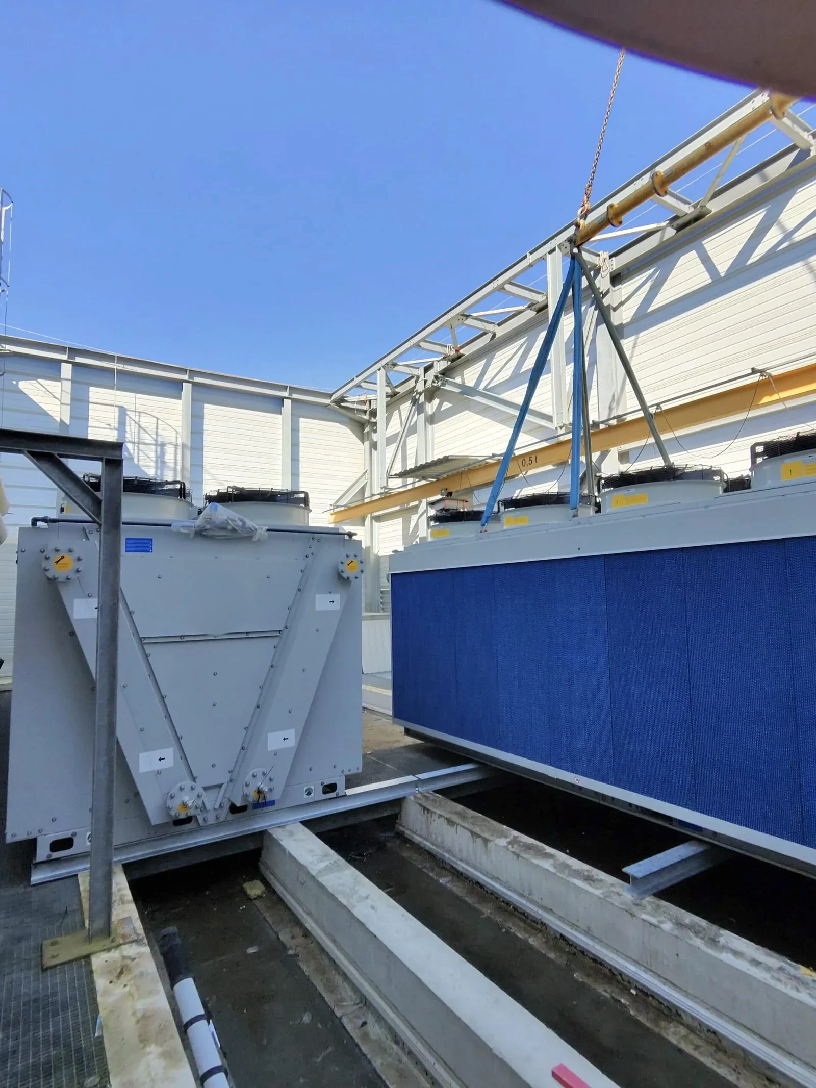
Adiabatic dry cooler
Replacing with .
Water consumption sharply reduced and the Legionella health risk removed.
- Glass manufacturing: cooling towers replaced
- Hospital: cooling towers replaced, installed by helicopter
Diagrams and technical data
- Principle: a dry cooler (finned coil + fans) whose incoming air is pre-cooled by evaporating water on a wet pad or by misting, only when it is hot.
- Water: consumption cut by 80 to 95% compared with an open cooling tower, no water circuit in contact with the discharged air.
- Health: no dispersion of warm water aerosols, so it can fall outside the cooling tower regulations (French heading 2921), to be confirmed site by site.
- Performance: in adiabatic mode, outlet water temperature around 3 to 5 °C above the air's wet-bulb temperature.
- Installation: on the roof or at ground level, by crane or helicopter; hydraulic connection possible by on the existing installation.
High-performance refrigeration
High-efficiency refrigeration systems, including transcritical CO₂ installations.
Low-impact and energy efficiency as a result.
- Overall optimisation of a refrigeration system
- Commercial refrigeration on CO₂
Diagrams and technical data
- Refrigerants: transcritical CO₂ (R744, = 1) or low-GWP refrigerants depending on the production temperature and the site.
- Efficiency: variable speed compressors, floating condensing, subcooling; the follows outdoor conditions instead of a fixed point.
- Recovery: on a CO₂ installation, the gas cooler provides high-temperature heat that is easy to turn into hot water.
- Regulatory: F-Gas compliance, leak checks and the refrigerant register kept by KELP Maintenances.
Floating high and low pressure control
Floating condensing pressure: the setpoint follows actual demand and the outdoor temperature rather than a fixed setting.
Savings obtained without changing the machine.
- Hospital: high / low pressure control
- Cold store: floating high pressure on a refrigeration plant
Diagrams and technical data
- Floating high pressure: the condensing setpoint follows the outdoor temperature instead of a fixed setting (often 40 to 45 °C all year round).
- Floating low pressure: the evaporating setpoint adapts to the actual load of the cold points.
- Order of magnitude: each degree of condensing temperature saved means about 2 to 3% less electricity at the compressor.
- Equipment: electronic controllers, pressure and temperature sensors, electronic expansion valves if needed; no change of machine.
Heat recovery
Recovering lost heat
A large share of the energy consumed on a site leaves as . Recovering it almost always costs less than producing more.
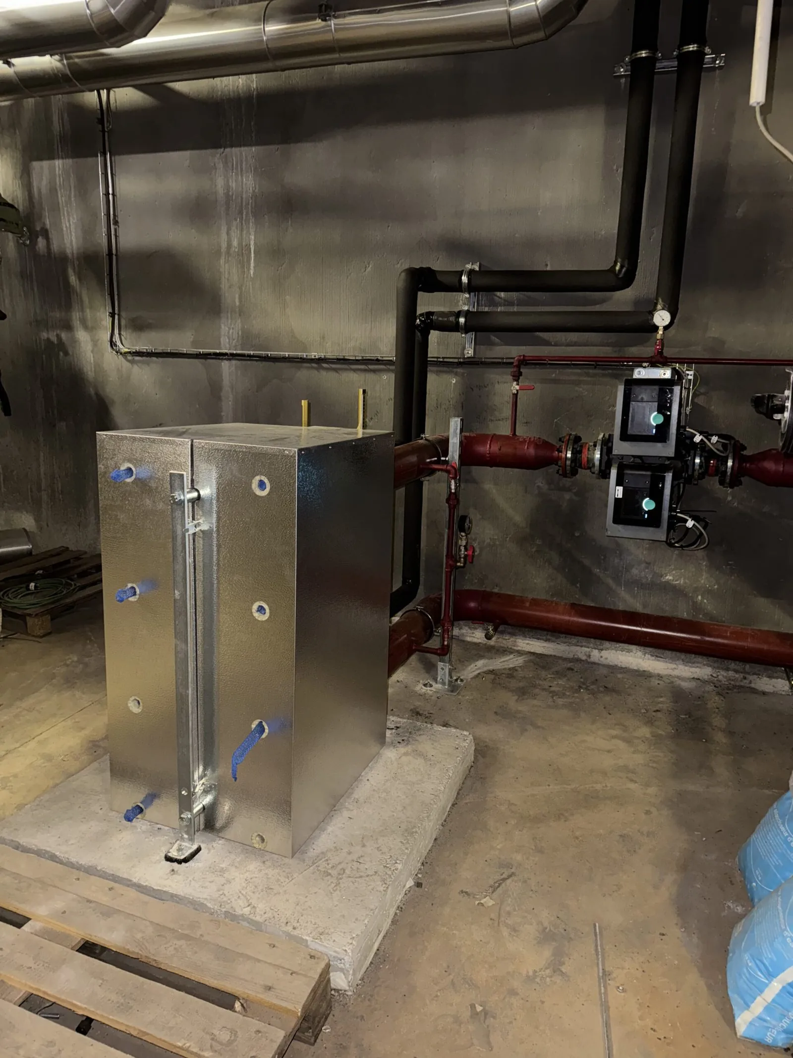
Heat recovery from chillers
A recovery installation captures the heat rejected at the ; a then transfers it to the or heating network. Connected by , without draining.
The heat is already produced: only the transfer remains to be funded.
- Hospitals: heat recovered from four to five into the domestic hot water networks
- Commercial refrigeration on CO₂ with
Diagrams and technical data
- Principle: a plate heat exchanger or a desuperheater captures the heat at the compressor discharge (hot gas at 60-90 °C) before the condenser.
- Use: preheating domestic hot water (from 10 °C up to 45-55 °C) or topping up a low-temperature heating network.
- Power: from a few tens to several hundred kW per chiller, depending on the installed cooling capacity.
- Connection: hot tapping (no draining), motorised three-way valves for bypass, storage tank to smooth out demand peaks.
- Effect: heat that was thrown outside replaces gas or electricity in the boiler room; the chiller, for its part, condenses better.
Heat recovery from industrial processes
Capturing heat from flue gases or production cooling circuits, then fed back to preheat air or water.
Several megawatts put to use where they used to be thrown away.
- Glass-ceramic manufacturer: 9,017 kW recovered from the and the , into twelve
Diagrams and technical data
- Sources: flue gases, process cooling water, hot air from compressors, vapours.
- : plate, shell-and-tube or heat pipe depending on temperature and fouling; materials suited to corrosive flue gases.
- Use: preheating fresh air for air handling units, process water or heating water; buffer storage if the needs are not simultaneous.
- Order of magnitude: several megawatts recoverable on an industrial site.
Heating networks and hydraulics
Distributing heat without losses
Between the boiler room and the emitters, a network loses heat, its pumps run too fast and distribution is unbalanced. Three simple measures fix this.
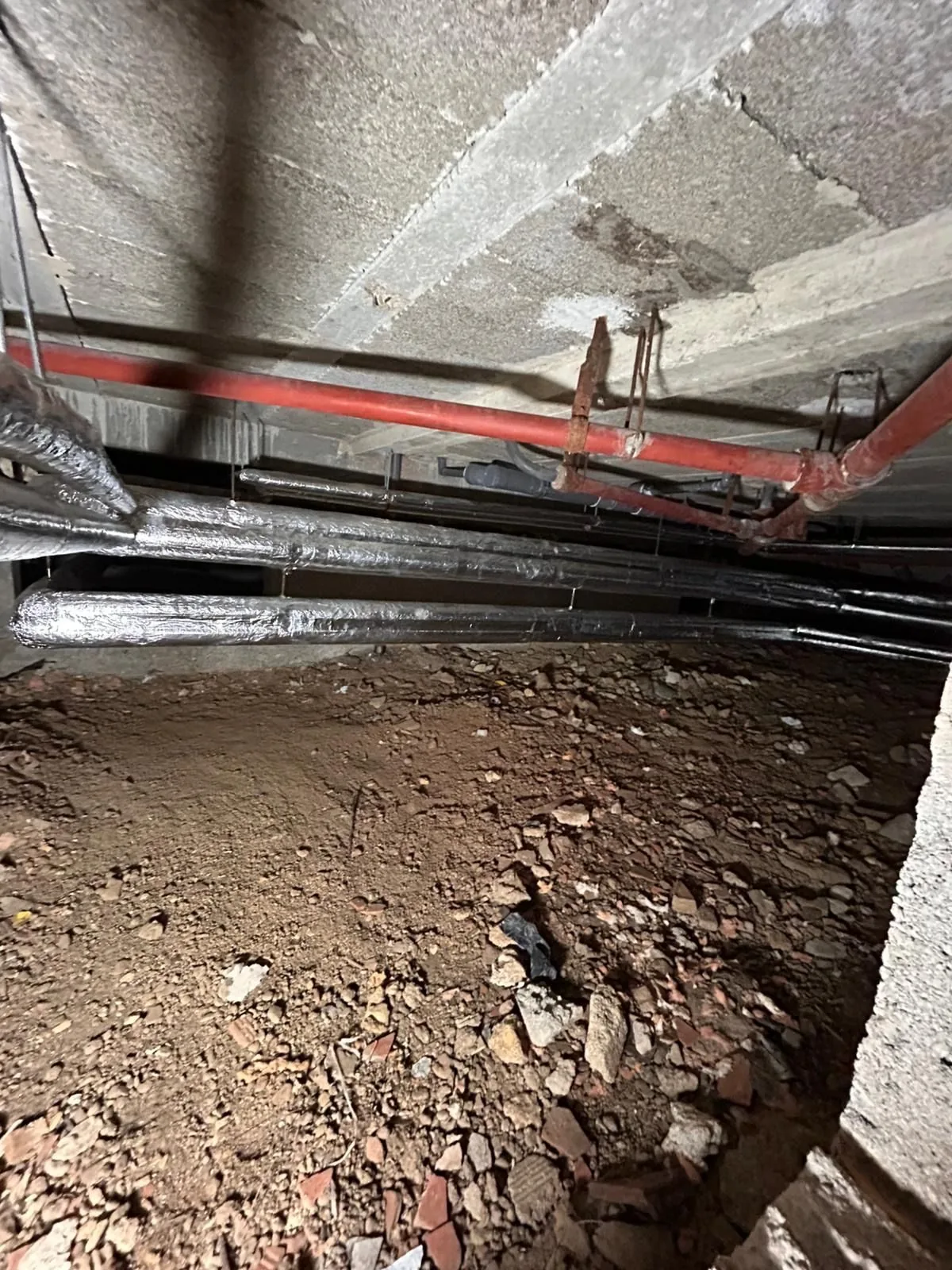
Pipe insulation
Insulation of fittings and uninsulated pipe runs: valves, flanges, take-offs, risers, crawl spaces.
One of the measures with the fastest payback, often eligible for .
- Public building: complete insulation of the heating network
- Hospital: insulation combined with
Diagrams and technical data
- Targets: valves, flanges, pumps, meters, riser take-offs, pipe runs in crawl spaces or plant rooms, often left bare after an intervention.
- Materials: mineral wool pipe sections, removable jackets on fittings, sheet metal or PVC finish depending on exposure.
- Order of magnitude: a bare DN100 valve on an 80 °C network loses as much as about 2 to 3 m of uninsulated pipe.
- Funding: standardised CEE operation (sheets BAT-TH-146 or IND-UT-131 depending on the site), application to be started before the works.
Balancing and terminal control
, , local room-by-room control.
Each zone is heated to its own setpoint, no longer the whole building to the most demanding one.
- Hospital: local control with thermostatic radiator valves
- Textile factory: thermostatic radiator valves and
Diagrams and technical data
- Thermostatic radiator valves: room-by-room setpoint, presettable heads to balance flow rates.
- Balancing valves: flow adjustment per riser so that the farthest emitters are supplied without overheating the nearest ones.
- Control: lowering the flow temperature (weather compensation curve) once the network is balanced.
- Order of magnitude: 1 °C less on the setpoint means about 7% less heating in the zone concerned.
High-efficiency pumping
Variable speed pumps slaved to the network's actual demand.
On a pump, a small reduction in speed brings a large reduction in consumption.
- High-efficiency pumping systems
Diagrams and technical data
- Equipment: pumps with permanent-magnet synchronous motors (IE5 class) and built-in , replacing fixed-speed pumps.
- Control: constant or proportional differential pressure, slaved to the network's valves.
- Physics: absorbed power varies with the cube of speed; cutting the flow rate by 20% nearly halves consumption.
- Funding: standardised operation depending on the context (building or industry).
Heat production
Producing heat at the best efficiency
Once has been recovered and the networks put right, a need remains. Replacing the production plant is the right time to change efficiency, not just the machine.
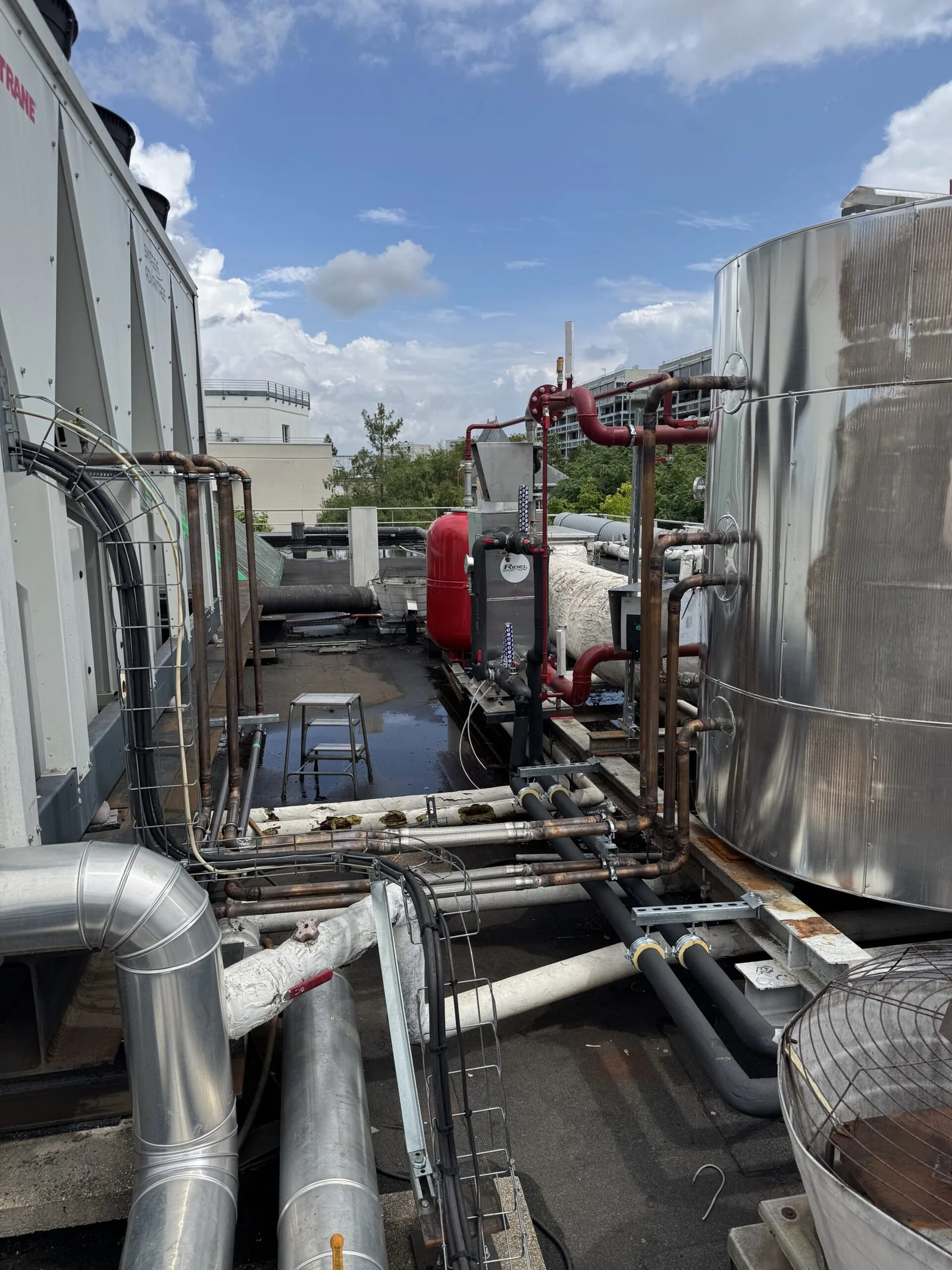
Heat pumps
Switching from gas to electricity to produce heat: building heating and hot water by , including high temperature and backing up an existing gas boiler.
Three to four times more heat for the same energy: 1 kWh of electricity yields 3 to 4, whereas 1 kWh of gas burned yields at best 1. Lower consumption, lower CO₂.
- Heating a public building with a heat pump
- High-efficiency condensing in a hospital
Diagrams and technical data
- Types: air-to-water, water-to-water (on a loop, groundwater or recovered heat), high temperature up to 70-80 °C to back up a boiler.
- Performance: seasonal of 3 to 4 in usual conditions; for the same heat, three to four times less energy than a gas boiler or an electric resistance.
- : R290 (propane), R32 or CO₂ depending on the target temperature and the capacity.
- Integration: backing up the existing boiler, with a buffer tank and changeover control based on outdoor temperature.
Air handling and HVAC
Treating the air and controlling the indoor climate
Comfort and production quality depend as much on the air as on the temperature. And poorly treated air is expensive.
Air handling units and dehumidification
and thermodynamic dehumidification, with recovery on the extract air.
Humidity under control without extra heating.
- Greenhouses: thermodynamic dehumidification
- Glass-ceramic manufacturer: twelve air handling units whose air is preheated by heat recovered from the and the
Diagrams and technical data
- Recovery: plate or thermal wheel on the extract air, 70 to 90% efficiency; fresh air arrives preheated.
- Thermodynamic dehumidification: water vapour is condensed on a cold coil and the recovered heat rewarms the air, without discharging warm humid air outside.
- Control: on humidity and temperature setpoints, variable speed fans.
- Uses: greenhouses, humid workshops, swimming pools, humidity-controlled rooms.
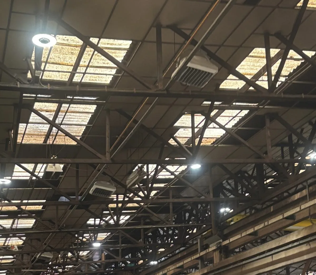
Air destratification
Evening out the temperature in large spaces, where heat collects under the roof.
The heat accumulated under the roof is brought back down to the occupied zone, instead of being produced at floor level.
- Metalworking site: 90 across seven buildings
- Concert hall, textile factory, metalworking halls: ceiling heights of 6.5 to 10 m
Diagrams and technical data
- The problem: in premises with ceiling heights of 6 to 13 m, warm air collects under the roof; the floor-to-ceiling difference commonly reaches 5 to 10 °C.
- Equipment: low-speed bladed destratification fans or air mixing columns, one unit for roughly 250 to 500 m² depending on the height.
- Control: high and low temperature sensors, speed control to bring the warm air back down to workstation level.
- Order of magnitude: up to 40% estimated saving on heating in large spaces (an estimate, not a measurement).
Control, monitoring and measurement
Controlling and measuring consumption
Without control and measurement, the savings achieved fade within months. It is also a regulatory obligation for commercial and public buildings in France (the ).
PLCs and BMS
: real-time supervision, time scheduling, alarms and consumption monitoring.
The answer to the , and the essential basis for any performance commitment.
- Multi-site supervision
- Regulatory compliance for commercial and public buildings (France, BACS Decree)
Diagrams and technical data
- Architecture: programmable logic controllers on each installation, centralised supervision, secure remote access.
- Open protocols: BACnet, Modbus, KNX, LonWorks; we integrate with what exists without replacing everything.
- Functions: time scheduling, setpoints per zone, optimised start-up, alarms, consumption history.
- BACS Decree: class B or A under the EN ISO 52120 standard, with monitoring and drift detection functions.
Variable speed drives
Matching motor power (pumps, fans, compressors) to actual demand, instead of running flat out or off.
On a motor, a small reduction in speed brings a large reduction in consumption.
- Automotive industry: electronic speed control on induction motors
Diagrams and technical data
- Principle: the motor speed follows actual demand (flow, pressure, temperature) instead of running flat out or off.
- Physics: on pumps and fans, power varies with the cube of speed.
- Equipment: frequency inverters with EMC filters, built-in motor protection, communication with the .
- Funding: standardised operation in industry (IND-UT-102 and following) depending on the motor power.
Sub-metering and measurement
Instrumentation per use and per workshop, following the ® protocol.
Control relies on measurement, and savings are verified.
- of energy savings
Diagrams and technical data
- Equipment: heat meters (flow meter + matched temperature sensors), electrical sub-meters per use, data loggers.
- Method: the IPMVP® protocol, option A (targeted measurement), B (full measurement) or C (whole-site consumption) depending on the scope.
- Adjustments: weather and activity effects neutralised by regression, to compare like with like.
- Deliverable: measurement and verification plan before the works, performance report afterwards.
Thermal equipment supply
The equipment we supply
Beyond our own projects, we supply heat rejection equipment and its spare parts. As a representative of the manufacturer Evapco, KELP Thermiques selects the right-sized unit for each site, from 100 kW to over 10 MW, oversees its commissioning and supports it throughout its operation.
Open cooling towers
Process or water is cooled in direct contact with the air. From 120 kW to over 10 MW per cell, outdoors or in a plant room.
AT, AT Atlas, AXS, ATP, LSTE, LPT
Evaporative closed-circuit coolers
The fluid stays in a closed circuit inside a sprayed coil: the process circuit is never contaminated. From 27 kW to 11 MW.
ATWB, eco-ATWB, ESW4, LSWE, LRWB
Hybrid, adiabatic and dry
Less water, or none at all: dry in mid-season, evaporative or adiabatic at peak, with no loss of capacity in summer.
eco-ATWB-H, eco-Air range (EAW)
Evaporative and air-cooled condensers
Condensing , from ammonia in industrial refrigeration to HFCs and HFOs.
ATC-E, eco-ATC, PMC-E, LSC-E, eco-Air
Ice storage
Cooling produced at night and released during the day: electrical peaks are shaved and the can be smaller.
ICE-PAK, Extra-Pak
Water treatment
Factory-fitted on the units: solid chemistry or chemical-free treatment, and less bleed-off water.
SmartShield, Pulse~Pure, Water Saver
Spare parts: genuine parts for installed units, and parts and maintenance contracts for multi-site fleets.
Custom-designed
Tailor-made solutions
The solutions above are the ones we have already installed and know how to reproduce. But no site is ever quite like another: an unusual heat source, a process that never stops, a boiler room to integrate, a performance commitment to honour. In that case the engineering office starts from your readings, not from a data sheet, and designs the answer.
To get started, contact the engineering office and tell us about your need, your issues and your site's situation. We can then carry out an audit, complete the information on site if needed, and make you a proposal.
Martin Coleau
Engineering & Innovation
Describe your need
The engineering office replies within 48 working hours to arrange a visit or a first conversation.
Financing
Some of these solutions qualify for energy savings certificates (CEE); other schemes exist depending on the site and the operation. KELP Énergies checks your eligibility and puts the application together for you.
Funding schemes